
How to Build a PC Controlled RC Car
August 2004
Update August 2012:
See the Programmable RC Car article for an updated version of this project.
This project article was originally written in 2004 when most computers had parallel ports. This is no longer the case, so much of this information is now outdated.
Introduction
The Mini RC Car Project has been one of my favorites to do. If you haven't checked that project out, please read through that one before starting on your own. I've gotten a few e-mails requesting a guide and since the software is done, all that is required is to construct the hardware. This is the second time I've done this project, using totally two completely different cars. The remote PCBs (electronics) were almost identical in both, so I'm assuming most all mini rc remotes are very similar, so this guide should be able to apply to all makes and models.
Tools and Materials Required
| - Mini RC Car & Remote - (5) Wires 1-2ft long (or 1 cat5 network cable) - Misc. small wires - Drill - Wire Stripper (or knife) - Screwdriver(s) -Scissors or Wire Cutters -Small piece of plastic or plexi-glass - *Some basic soldering skills |
- Soldering Iron - Solder - (4) 2N3904 NPN Transistors - (1) Small solder board - Male Parallel Port Connector - Digitial Multimeter if Avaliable Total Cost: (not including tools) Approx - $20.00 cdn |
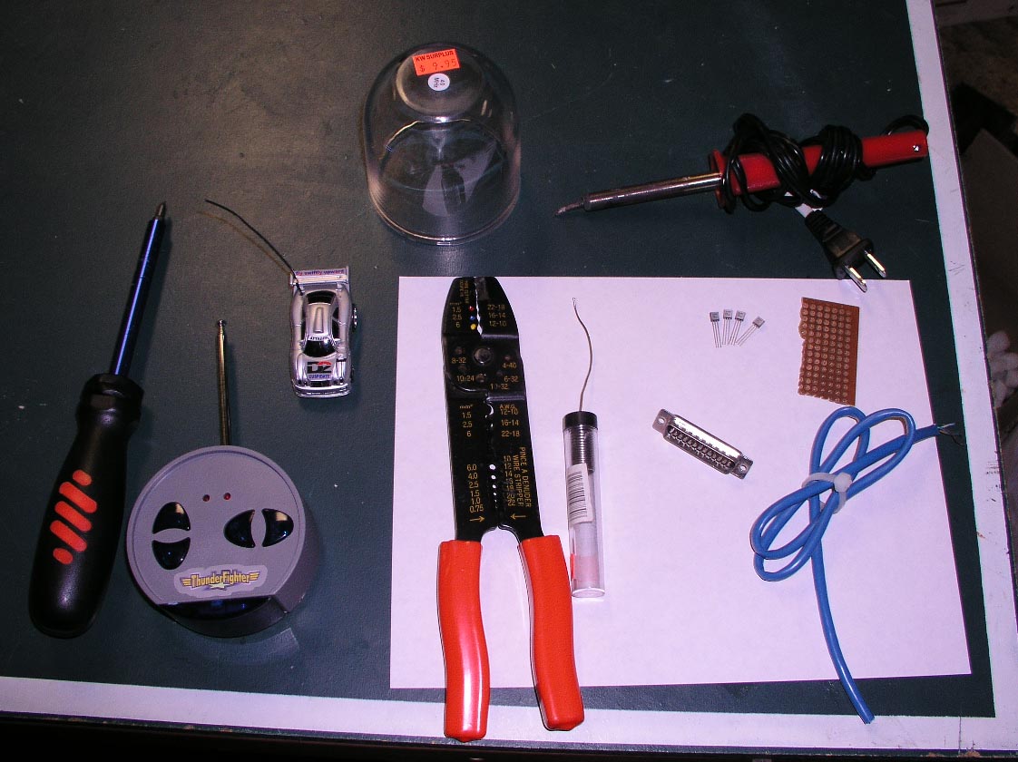 (Most of the tools required, all laid out) |
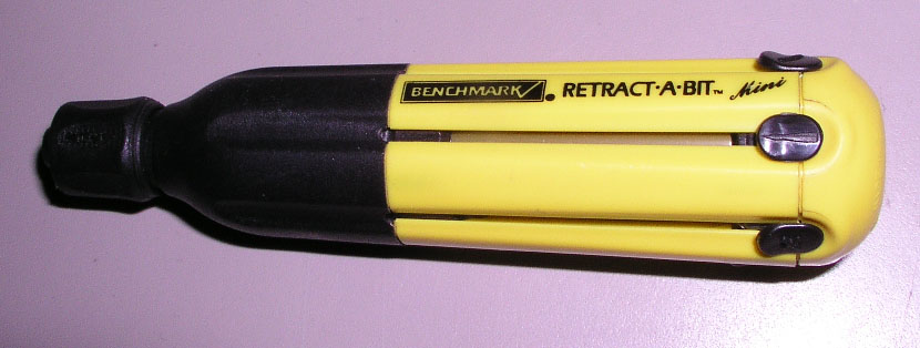 (Retract-a-bit Mini Screw Driver. Very Useful) |
 Transistors and Solder Board |
|
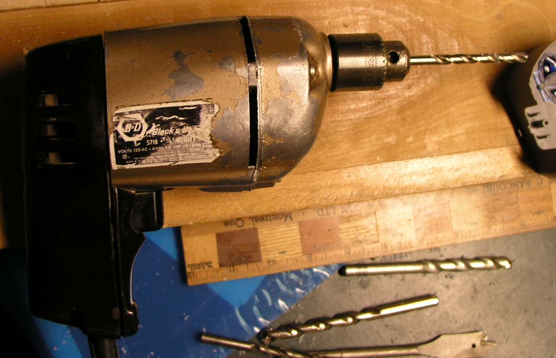 Drill |

Step One: Open Remote and Expose PCB
With the antena unscrewed, remove the 3 screws from the back of the remote. You will need a fairly small screwdriver.
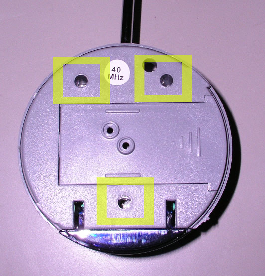 1 - Screw Hole Locations |
 2 - Buttons and Screw |
 3 - Attached still |
 4 - The PCB is free |
The following corresponds to the pictures
above:
1 - Screw Hole Locations
Remove the screws and the remote face
should come off easily.
2- Take note of the button locations
and remove the bottom right screw holding
the PCB in place.
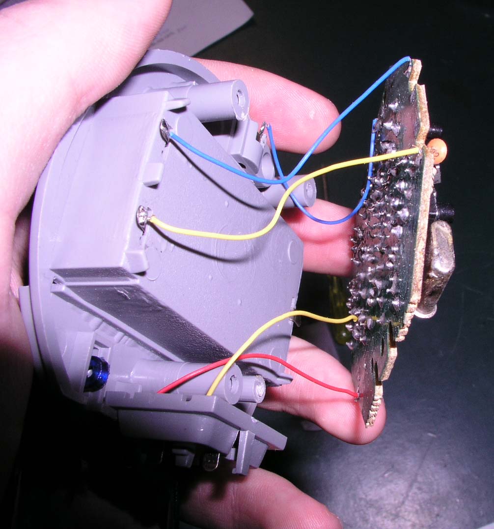
3- The PCB is still attached. Snip
the wires close to the circuit board,
but leave enough of the wire to identify
the colour, for when re-attaching later.
4- The PCB should now be free,
making it easier to work on.
Step Two: Drilling the Remote Case
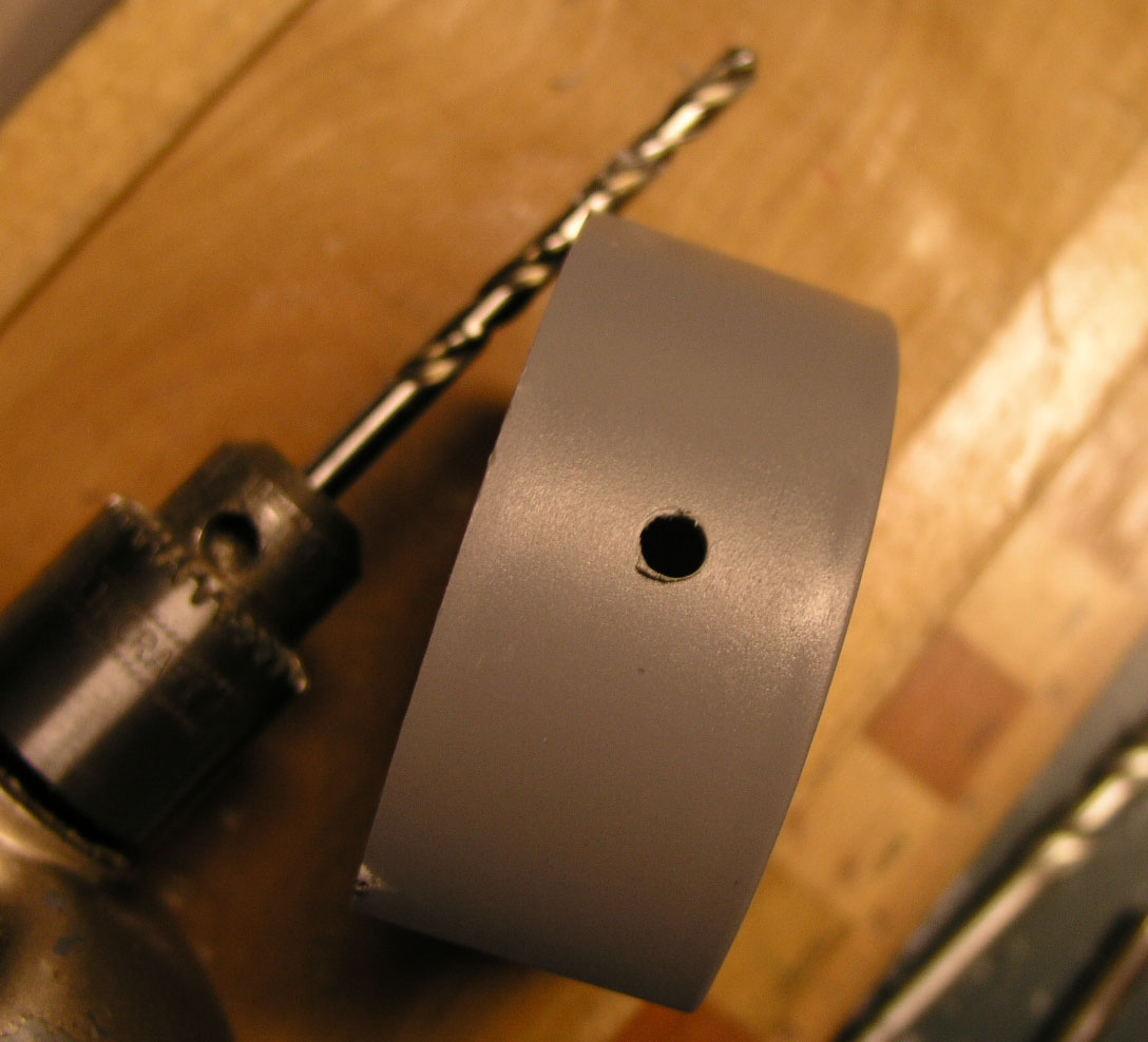 |
In order to get a cable that goes from the back of the remote's PCB to the computer, we need to make a hole in the remote's plastic case for the wires to go through. Any size hole will do, as long as it's big enough for your wires to fit through. Drill the hole closer to the back of the remote, if possible. That just makes it so the cable won't have to bend as much. |
Step Three: Soldering to the Board
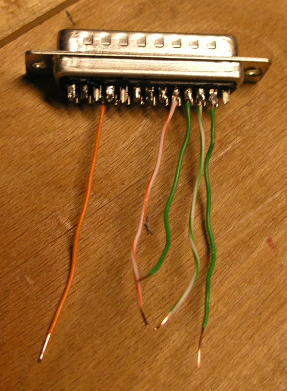
| Strip the ends of the wires. Five wires, about 1-2 ft in length are needed. I used a Cat-5 network cable that has 8 wires in it, but only 5 are required. |  |
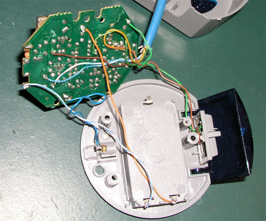
| Turn over the PCB (printed circuit board). Under each button there are four solder joints. These are actually (2) sets of (2) joints. These are highlighted in the picture on the right. Identify the wire that the negative side of the battery was connected to (see wire indicated in the picture). This will connect to one of the large green areas on the board. For each switch, two of the solder joints will be located in this green region. Leave those joints alone. | 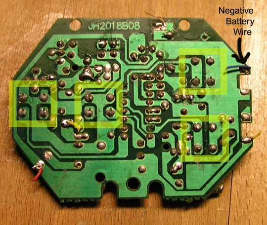 (Click for a Larger Image) |
 (Click for a Larger Image) |
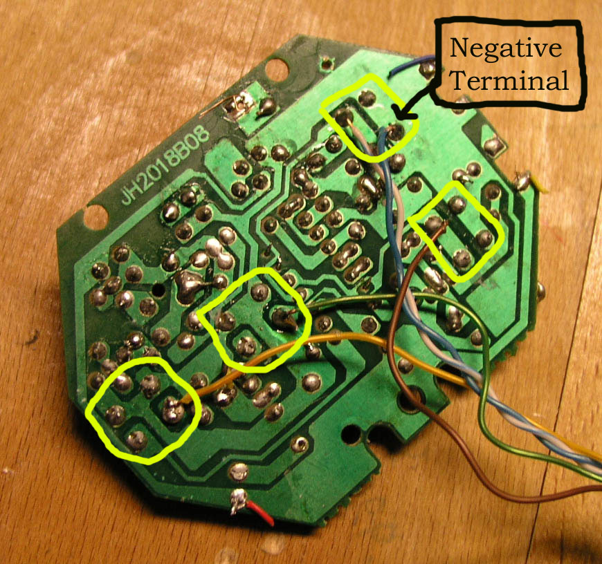
What we are concerned with, is the positive "side" of the switch. For each switch, you need to identify which side is negative and which is positive. Solder a wire onto each positive side and one wire to a negative terminal (there are many negative terminals on the PCB, it doesn't matter which you choose). You should have 1 wire per switch soldered, and one wire to the negative terminal. My board, with the wires soldered can be seen to the left. Boxes are drawn in to show the same groups of four shown above. |
Step Four: Build the PC Interface
This is the most callenging part of
the project.
Before you start building the cable, feed
the wires you soldered, through the hole
you drilled earlier. This will allow you
to put it all back together again at the
end.
 |
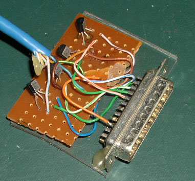
Take the male parallel port connector and solder short wires to pins 2,3,4,5,23. Pins 2-4 will carry the data (forward, reverse, left, right) and pin 23 is ground. Side note: when doing any pc-parallel port interfacing, pins 2-9 are easily controlled data pins and pins 18-25 are all ground. Other pins have specialty functions and can be used in interesting ways. When completed, it should look similar to the picture on the left. |
|
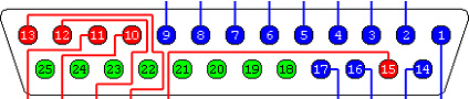 |
Parallel Port Pinout (Click for Larger Image) |
|
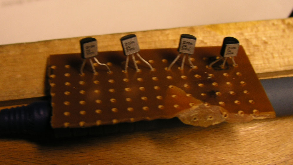
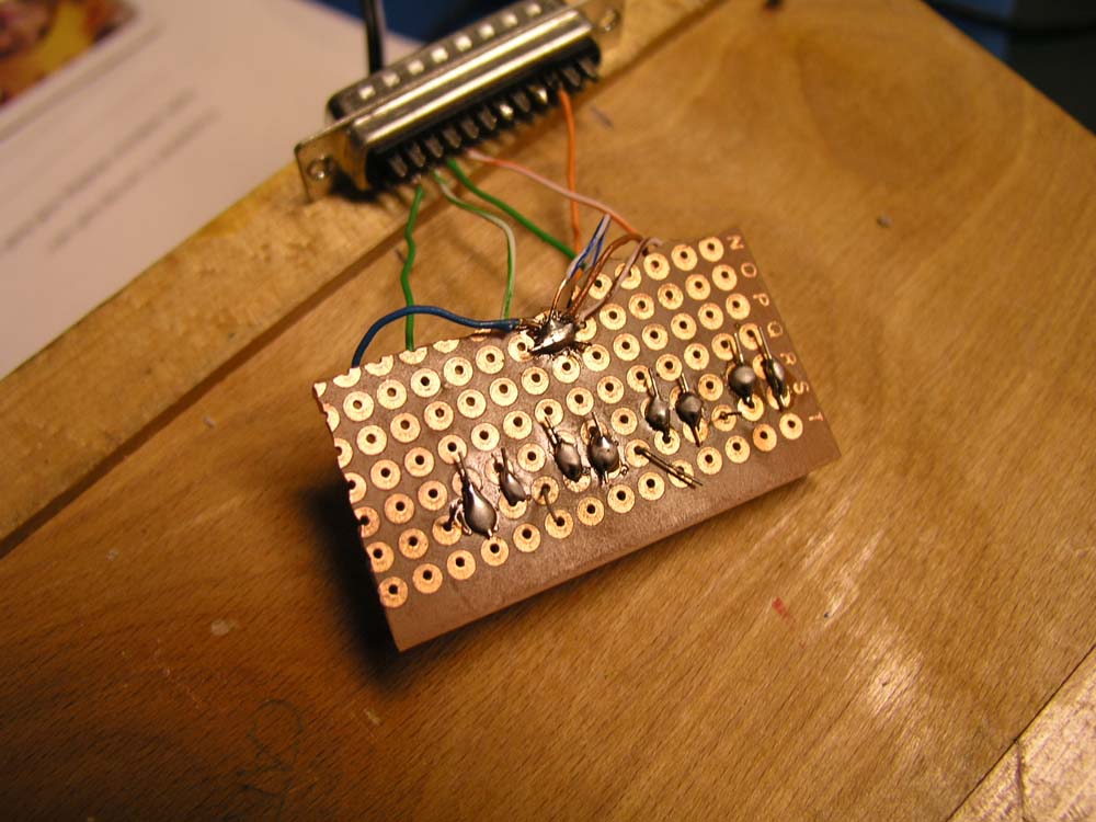
The rest consists on building a circuit, using the schematic (diagram) I have made up. For this you need, a bunch of small wires, solder board, (4) 2N3904 NPN Transistors. Print out the schematic below and build the circuit. (Note: the ground is the Parallel Port Pin 23 and Remote Negative Terminal connected together, there is no 'third' ground.)
 (Click for a Larger Image) |
Pictures of Circuit Construction:
Follow the schematic, but these may help you
out. These pics do not show full construction.
|
 |
 |
 |
If you've followed the schematic and completed the following steps properly, all we have left to do is re-attach the wires cut at the beginning and put everything back together.
Step Five: Reattaching the Wires
In the first step, you cut some wires. Those will now need to be re-attached. I would suggest replacing them with your own wires and use longer ones. The factory wires are very cheap and it's a lot easier just to use wires double as long, so you have enough room to solder them to where the old wires use to be. You can always just strip the old wires are re-attach using electrical tape, but I think my way is easier. The choice is up to you.
Step Six: Reassembly
 |
The remote needs to be re-assemled. Squish down all the wires down on the back of the PCB and put the screw back in. It might take several tries to get it flat enough, because there's a lot more wires back there than there use to be. Put back on the plastic remote face and replace the screws in the back of the remote. The remote should look very much like how it started, but with a large bunch of wires sticking out the side. |
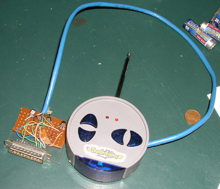 |
After the remote is put back together, the hardware aspect of the project is complete! |
Making it Look Nice
 |
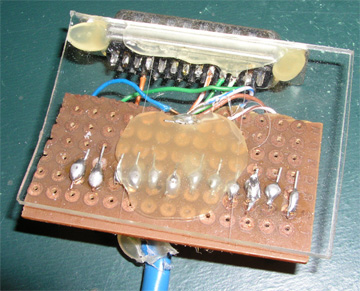
To make it easier to plug in, it's best to have a solid unit to plug into the back of the computer. I took a small piece of plexi-glass and glued all the components to it to make it sturdier, easier to handle and it makes it look a whole lot better. |
 |
Software
The remote will still function normally if you use it just by pressing the buttons, but to control it with the computer, software is needed. For my grade 11 final computer science project, I built this hardware and wrote the software to control it. To control what you've just constructed, you will need the software as well. It is avaliable here. To make the software work, you need to know the port address of your parallel port. In the documention included (documention.doc, in the zip file), there are clear instructions how to find this address. The most common address (888) is the default. The software was written in Visual Basic 6, and was recently updated to run on all windows operating systems.
Source code for a similar, but simpler example program can be found here (also written in VB6).
Quick Lesson: How it Works
With the software, the computer sends a signal from the parallel port to the transistor. The transistor closes the circuit between the ground and the positive side of the button switch. This is the exact same thing that happens when you press the button manually. So essentially, the computer is pressing the buttons for you. Because we can control the computer, it means we can make the car programmable and other neat stuff like that.
Conclusion
I hope you've enjoyed this guide and learned something along the way. If you do construct your own Computer Controlled RC Car, and send me a pic I will post in on the site. If you have any feedback or questions let me know and I'll be glad to help. If you have any difficulties along the way, let me know and I'll try to help you out. Controlling the parallel port is quite easy and it opens to door to a whole lot of PC-Hardware interfacing. With transistors, you can control motors or other electronics. My latest pc interfacing project was my grade 12 computer science project, which was to control an LED matrix of 140 LEDs, with just the handful out outputs of the parallel port (some additional electronics were required). That project will soon be posted in the projects section.