
Programmable RC Car: How-To Guide
August 2012
|

| Introduction Software Hardware - How-to Guide |
Introduction
This Programmable RC Car is a modified $9 toy bought online. Complex control sequences can be programmed or it can be controlled using the keyboard (or gamepad). This guide will show you how to build one yourself! This is an excellent beginner electronics project (with some soldering required).
All software and hardware schematics are open-source. The software is written in Java and runs on Mac, Windows, and Linux. This project uses an Arduino (via USB). A similar project I completed in 2003 used the PC parallel port.
Software
RC Controller GUI
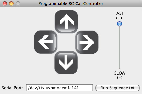

Clicking on the Serial Port text box will open a selection dialog which lists all detected serial ports. The Arduino UNO lists itself as a usb modem as shown above (on Mac).
Programming a Control Sequence
(sequence.txt)
# Programmable Sequence File
#
# Directions
# FF = Forward, FR = Forward & Right, BB = Backward, etc.
# SS = Stop
#
# FL FF FR
# LL SS RR
# BL BB BR
#
# Invalid Directions: FB, LR
#
# Format:
# <Direction>, <Speed: Range 0 - 255>, <Duration in Milliseconds>
#
# Ex: FF, 255, 100
# Drives forward at full speed (255) for 100 ms
#
FL, 255, 250
FR, 255, 400
FL, 255, 100
The file sequence.txt is included with the software. Complex control sequences can be programmed using the syntax shown above. Lines that start with # are comments.
Arduino Code
This code receives data from the Arduino's serial port, processes it, and controls the Arduino's pins to drive the RC car.
Download
The source code is well commented and should be easy to undertand. The GitHub repo contains source code and compiled binaries.
Some Software Details
The cross-platform RXTX Comm library is used for serial port detection and communication. The GUI sends commands to the Arduino through through the serial port, which intereprets the commands and controls the RC car.
Loading Arduino Code
See this getting started guide for how to load the code onto an Arduino board.
Speed Control - Pulse Width Modulation (PWM)
Speed control is achieved using PWM. This basically simulates pressing the buttons really fast, but varying the ratio of the on and off button state to modulate speed.
Hardware
Parts Required

Part |
Quantity |
Part Number |
Cost |
Source |
| RC Car* | 1 |
20644 |
8.99 |
|
| Arduino (model UNO used) | 1 |
1050-1024-ND |
26.56 |
|
| ULN2803A IC | 1 |
497-2356-5-ND |
0.93 |
|
| DIP Chip Socket | 1 |
A100207-ND |
0.28 |
|
| Solder Board | 1 |
V2025-ND |
6.26 |
|
| Male 0.1" Header (8 pin) | 2 |
609-3264-ND |
0.27 x 2 |
|
| Female 0.1" Header (8 pin) | 1 |
S7006-ND |
0.85 |
|
| Total (USD) | $44.41 |
*This project can be completed using any RC car that has a remote with 4 directional controls.
Note
You will also need a few wires, solder and (optionally) zipties. I also recommend buying a few extra of the cheap components above in case any are damaged during project construction.
Tools Required
- Soldering Iron
- Multimeter
- Screw Driver
- Optional: wire stripper, wire cutter, hot glue gun
How-To Guide
Step 1 - Disassemble the Remote


There are a few screws to remove. One of them is in the battery compartment.
Step 2 - Remove PCB

You'll need to de-solder the battery connection wires to remove the PCB from the remote's plastic case. Remove the screws holding in the PCB and it should come away freely.
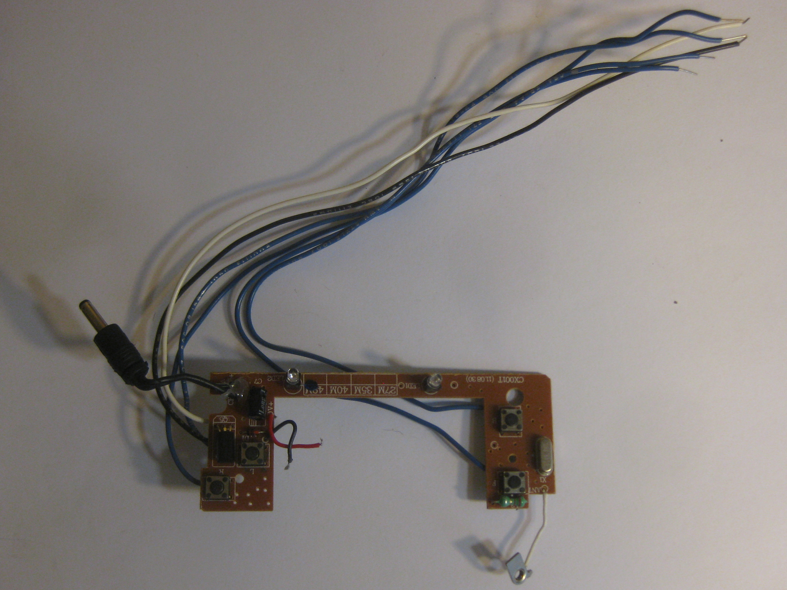
Step 3 - Solder Wires to Remote PCB

Solder 2 wires to where the battery connections meet the PCB. I chose white for +3V and black for GND.
Next, solder 1 wire to each button location. You'll have to find the right pad to solder to. You can determine which pad is correct by testing pads near/underneath the physical button switches seen on the other side of the PCB. When the button is pressed, the correct pad will be connected to GND through the switch. By using a multimeter's resistence setting or it's continuity mode, you can determine which pads get connected to GND on the button press.
You should have 6 wires connected to your PCB. This is the most difficult part of this project.
Step 4 - Build the Circuit and Test!

Note
The Arduino's 3.3V is close enough to the remote's 3V batteries that we won't bother with voltage regulation.
This schematic was created using Upverter - a great (and free) online tool for building open-source hardware. Feel free to fork and improve the design!

You should have the Arduino code loaded on to your board. If not, scroll up to the software section and complete that step. Build the circuit as shown above. Make sure the RC car is charged and will move when you push a button on the remote. If it doesn't, check that your circuit has power.
Run the software and GO! After launching the software and selecting your serial port, you should be able to drive the car using the computer.
Step 4 - Start to Assemble the Arduino Shield


Place the header connectors in the black Arduino connectors and solder in place as shown.


Insert the chip socket roughly in the middle of the board and solder it in place as shown.
Tip
Use a chip socket when using an integrated circuit (IC) in a prototyping design. This saves lots of time in the event that the IC is damaged or doesn't work as expected.
Step 5 - Solder Chip -> Arduino Connections


Solder the chip to Arduino connections as listed below and shown above.
Arduino |
ULN2803A |
3.3V |
Pin 10 (Vs) |
GND |
Pin 9 (GND) |
Digital Pin 9 |
Pin 2 |
Digital Pin 10 |
Pin 3 |
Digital Pin 11 |
Pin 4 |
Digital Pin 12 |
Pin 5 |
Step 6 - Wire Up the Cable


Solder 4 long wires (~20 cm) connected to pins 2 - 4 of the UNL2803A IC. Solder 2 long power wires as shown above.


This is a good time to re-test your circuit and ensure that all connections have been made correctly. You can make the clean up cable wires with zipties as shown above.
Step 7 - Solder Male Connector


Tip
Tinning the wires and connector pins as shown above makes soldering to connectors easier.
The order of the of the wires from right to left is 3.3V (white), GND (black), Arduino Pins 9 (blue), 10 (blue), 11 (blue), and 12 (blue).
Step 8 - Re-assemble the Remote

Place the PCB back in the remote case, re-solder the battery connection wires, and secure the PCB with the screws removed earlier.


Fully re-assemble the rest of the remote. This is a good time to re-test your circuit to ensure no connections have come loose.
Tip
I removed some plastic from the inside of the case to allow more space for the wires to exit the remote. Also, the unmodified remote had a plastic cover covering the charging port that I did not reuse when reassembling the remote.
Step 9 - Assemble Female Connector


Following the same procedure outlined in Step 7, cut the wires to length and solder them to the female connector. I used hot glue to attach the connector to the remote case. The wire ordering shown in the right picture is from left to right is 3V (white), GND (black), Forward Switch (blue), Backward Switch (blue), Left Switch (blue), and Right Switch (blue).
Step 10 - Plug In and Go!

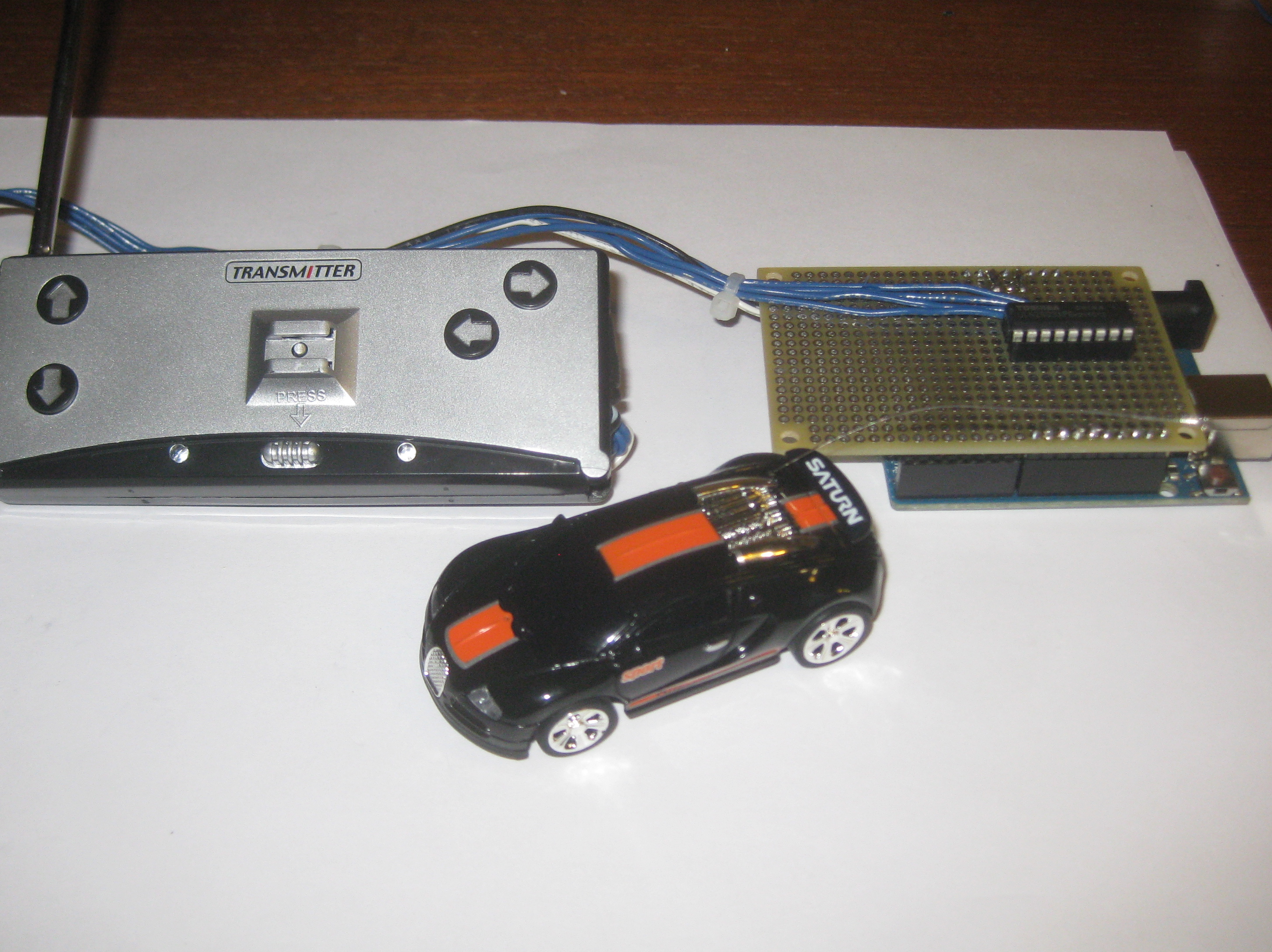
Plug in your shield cable to your remote's connector, plug in your USB Arduino, fire up the software, and GO!
Questions or Comments?
Comment below or contact me at .