
LED Matrix
Computer Controlled
September 2004
Introduction
As a personal project in grade 12, I decided to
build an LED Matrix and write the software to control it. I was
able to submit the software for my grade 12 computer science final
project, so that worked out well. When I first started looking
into how to do this, I wanted to control every light individually.
Since the parallel port has less than 12 outputs, additional electronics
would be required to control more than 12 LEDs (light emitting
diodes, tiny light bulbs).

Below I will describe the approaches I had to solve the problem, as well as the final solution.
Approach 1: Address Each LED Individually
I was hoping that using shift registers, or some other electronics I haven't used before ... that I could send a series of pulses of information, and then through the electronics, each LED would be able to be controlled individually. I haven't used shift registers before, and it would require buying 100 LEDs (10x10 matrix), soldering them all individually and there would be a lot of additional electronics required by this approach. Also, when looking on the net ... other people who have done similar projects have not used a massive ammount of electronics.
Approach 2: Use a Commercial Solution
 |
5x7 LED boards are used all time in Pinball and Arcade Machines. In the Monopoly Pinball machine, they scroll pictures of houses and other small graphics like that accross the screen. That's what I wanted to be able to do with my display. After looking around on the web, I found a company that makes a chip to control 5x7 LED Modules. That is Maxim-IC's MAX6952 chip. After trying to buy the chip locally, I couldn't find it, so I went to the company's website and they ship free samples. So I got a couple sample chips for free. I followed the company's wiring diagram and used their test software, but for whatever reason I couldn't get the display to light up. Their chip has a built in font-set which might not allow custom graphics. Also, their chip has a serial interface which I haven't worked with before, and I'm guessing that it would be hard in Visual Basic to get the timing right to get the parallel port to "talk" to their chip. This approach is really the lazy way out, because if everything worked properly, programming it would be very easy. But it wouldn't allow the flexibility of each LED being controlled individually. |
Approach 3: Custom Software, Nifty Electronics [Scanning Method]
After I wan't able to get the MAX6952 chip to work, knew I had to figure out my own solution. The way that a TV or computer monitor works, is by a beam scaning across the screen from top to bottom, many times a second. So fast, that it appears to be a solid or moving image in front of your eyes. That is the method that was used with my LED Matrix. One coloumn is selected, certain LEDs are turned on in that coloumn, and then the next column is selected, and so on. This is done many times per second, which makes it appear as if there is a solid or moving image. I didn't want to go this route, because the programming is probably the most difficult of the 3 approaches.
How it Works
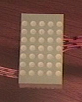
I used (2) 5x7 LED Displays, so 10 columns and 7 rows for a total of 70 LEDs. As mentioned before, the matrix works on the basis of scanning the display very quickly. I used the 4017 chip to switch between the columns. The way the 4017 chip works, is that when a signal is sent to a certain pin, 1 of 10 of the other pins is sequentially activated. The way the software works, is it tells the chip to switch columns, which sets one column high. The software then makes the parallel port turn on the individual LEDs in that column needed. This is done very quickly, many times a second. It's a fairly easy concept and it turned out the programming was easier than I had initially anticipated.
Construction
 |
The project required 10 transistors and 10 resistors. I probably shouldn't have put all the transistors so close together, because it made them quite difficult to solder. It worked out ok in the end though. The parallel port sends a signal to the transistor, the transistor acts as a switch so that the external power supply can give the current needed to light up the LEDs. The parallel port does not have the amperage required to power 7 LEDs brightly. |
 |
This is the clip for the external power supply. 5-6 Volts is connected and that powers the (2) 5x7 LED Matrix displays. |
 |
This is the 4017 chip that is used to switch between the columns. After soldering all the wires, the chip was extremely hot! I'm just glad I didn't fry it. |
 |
Parallel port connector. This is the part of the project that gets plugged into the computer. |
 |
Here's the back of the board where you can see all of my soldering. I'm not a soldering guru, but at least it's functional. I covered all the connections with glue, so that no one would accidentally placed it on a metal surface when it was on or something. |
 |
The final product. The massive ammount of wires required are held out of the way by wire ties. If I had gone with approach 1, discussed above, there would have been 10x the ammount of wires and electronics. |
Display Pictures
 This a custom graphic I drew using the font designer. |
 . |
The columns with less LEDs lit are brighter, because the same ammount of current that is going through 7 LEDs in column 6, is going through 1 LED in column 1 |
Scrolling Videos
Quicktime Player required, download
it here if needed.
To Download Movie: Right-Click, "Save-Target-As"...
GoLeafs.mov 4 seconds, 1.19MB Go Leafs Go! Scrolled |
HeartScroll.mov 6 seconds, 1.68MB A heart, scrolled |
jb2.mov 2 seconds, 570KB JB Graphic, Scrolled |
Movie Mode Movies
These movies were made using the movie-mode function of the software.
(more about that below)
zoom.mov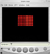 8 seconds, 2.28MB Zoom affect. Nifty. |
bball.mov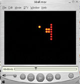 3 seconds, 929KB Quick Basketball Shot |
snake.mov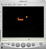 4 seconds, 1.17MB Quick snake Game. |
Software
The software is what makes this all work. It was programmed in Visual Basic 6 and the commented source code is avaliable below. The biggest problem with programming this was getting the timing correctly. Windows 98 and Win2k/XP handle timing calls differently and the smallest timing division can be as large as 55ms. This means that to switch a coloumn, it would take 55ms, which means it would take 1/2 second to scan through the display once ... for a refresh rate of 2Hz, which is very slow. I found a control that worked in Windows 98 which supposedly had a resolution of 1ms, but in practice it was not that low. That same timer had a resolution of 55ms in 2K/XP! Currently I'm using the QueryPerformanceCounter timer, which seems to be working well in Win2K. I was using the TimeGetTime counter for Windows 98.
Problems with the software:
![]() Flickering
- Flickers when scrolling large messages (see Go Leafs Go! video)
Flickering
- Flickers when scrolling large messages (see Go Leafs Go! video)
![]() Software should
be re-written using threads. Then the CPU isn't tied up so much
when running the main loop when scrolling.
Software should
be re-written using threads. Then the CPU isn't tied up so much
when running the main loop when scrolling.
 |
LED Matrix Controller With the movie mode function, a "scene" (10x7 picture) is taken from movie.txt and the display is refreshed with new scenes as required. |
 |
Font Designer The second program I wrote for this project was the Font Designer. For each character (a,b,c,A,B,C,1,2,3...) I had to figure out which LEDs needed to be turned on. Then after that was determined, that needed to be translated into the "code" that the matrix controller reads from the text file. To speed up the process, I wrote the font designer. The faux LEDs can be turned on and off just by clicking on them, when a letter or picture is completed, you just hit "Code It" and then copy that code into fonts.txt. Whenever the unique identifier appears in the message box of the matrix controller, whatever picture was drawn in the font designer, shows up on the actual LED display. |
Download the software source code (written in VB6).
Possible Applications:
| - LED Clock - Message Scroller - Hook it up to a microcontroller, so no PC is required. |
- Simple Movie Display - Simple game display (ie Pong) |
Project Costs
| Item: | Cost: (cdn) |
| Solder breadboard | 7.00 |
| Wires, wireclip and parallel port connector | 2.00 |
| (2) 5x7 LED Matrix Displays | 10.00 |
| Transistors | 1.50 |
| Resistors | 1.00 |
| 4017 Chip | 1.00 |
| Tax (15%) | 3.38 |
| Total: | $25.88 |
Conclusion
I've been thinking about doing an LED matrix for quite a while. I'm pleased with the way it turned out, and I'm glad I didn't have to solder 70 LEDs individually. The software has room to improve, but it's up to "proof of concept" standards. If I ever start messing around with microcontrollers, hooking this up to one could be a really neat project. With the current hardware and software, it wouldn't be hard to double the size of the matrix to 20x7, instead of 10x7. That would allow for a lot more to be displayed at once. If there's a lot of interest, I might even make a how-to guide like I did for the PC Controlled RC Car, so if you want one, let me know.
Resources
| Description | Link |
| LED Matrix Clock using a Maxim-IC Chip | |
| 16x16 LED Matrix, each LED hand soldered. Was a university project for him in the 80s. Microcontroller used. | |
| LED Matrix Tutorial. It got me thinking about how to do the project using the scanning method, described as "persistance of vision" | |
| LED Sign using 4017's and scanning. Has a good explanation of the scanning method. | |
| LED Matrix Pong! So Awesome. Check it out! Also a cool projector project there as well. | |
| Maxim-IC's product page for the MAX6952 chip. You can also get free samples from them. | |
| Information about the QueryPerformanceCounter I'm currently using. | |
| Pinout of the 4017 Decade Counter. | link (scroll down) |